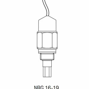
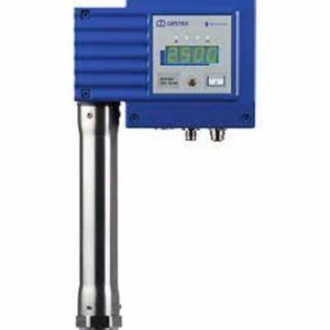
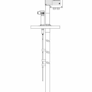
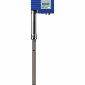
Cảm biến đo mức Gestra NRGT 26-1 NRGT 26-1S For Marine Applications

Technical data
Service pressure
PN 40, 32 bar at 238°C
Mechanical connection
NRGT 26-61: Screwed G 3⁄4 A, ISO 228
NRGT 26-61S: Flange DN 50, PN 40, DIN EN 1092-01
Materials
Screw-in body: 1.4571, X6CrNiMoTi17-12-2 Electrode rod insulation: PTFE
Terminal box: 3.2161 G AlSi8Cu3
NRGT 26-1S: Flange 1.0460 P250GH
NRGT 26-1S: Spacer disc: PTFE
Length of installation / measuring range
|
NRGT 26-1 |
NRGT 26-1S |
||
|
Length of instal- lation at 238° C |
Measuring range |
Length of instal- lation at 238° C |
Measuring range |
|
373 |
300 |
316 |
275 |
|
477 |
400 |
420 |
375 |
|
583 |
500 |
526 |
475 |
|
688 |
600 |
631 |
575 |
|
794 |
700 |
737 |
675 |
|
899 |
800 |
842 |
775 |
|
1004 |
900 |
947 |
875 |
|
1110 |
1000 |
1053 |
975 |
|
1214 |
1100 |
1157 |
1075 |
|
1319 |
1200 |
1262 |
1175 |
|
1423 |
1300 |
1366 |
1275 |
|
1528 |
1400 |
1471 |
1375 |
|
1636 |
1500 |
1579 |
1475 |
|
2156 |
2000 |
2099 |
1975 |
Weight
NRGT 26-61: approx. 1.8 kg
NRGT 26-61S: approx. 8.0 kg
Electronic circuit board Supply voltage
24 V AC/DC
AC +/– 20%
DC +10 / –45%
115 V +/– 10%, 50/60 Hz (option) 230 V +/– 10 %, 50/60 Hz (option)
Power consumption
3 VA at 24 V DC
5 VA at 24, 115, 230 V AC
Fuse
External slow-blow 0.5 A
Internal thermal fuse Tmax = 102°C
Sensitivity of response
Range 1: Water ≥ 20 μS/cm
Range 2: Water ≥ 0.5 μS/cm
Range 3: Fuel oil EL, dielectric constant εr 2,3
Output
Actual value output 4 – 20 mA, level proportional. Electrically insulated, max. load 500 Ω
Thông tin liên hệ
Công ty TNHH Nhiệt Cơ Điện Non Nước
Hotline: O9O9 773 479
Email: info@nonnuoc.com.vn
Website: www.nonnuoc.com.vn
Theo dõi chúng tôi trên các mạng xã hội: