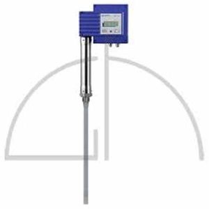
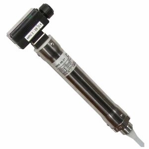
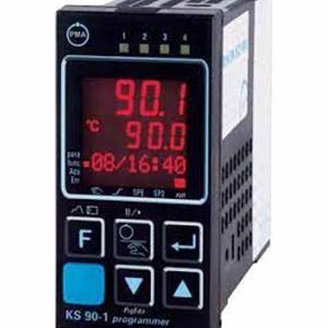
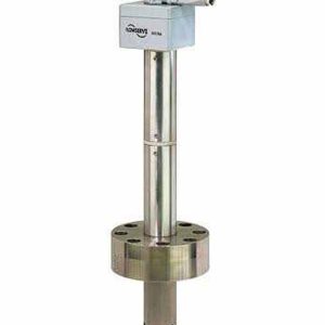
Cảm biến đo mức nước Gestra NRG 16-38 S, NRG 16-39 S

Technical Data
Design
NRG 16-38S
1 Level electrode NRG 16-11
1 STARLOCK® retaining ring 11.5/4.8
1 Level transmitter NRGT 26-1S
Both level electrodes are installed in one common ange DN 100.
NRG 16-38S
2 Level electrodes NRG 16-11
2 STARLOCK® retaining rings 11.5/4.8 1 Level transmitter NRGT 26-1S
All level electrodes are installed in one common ange DN 150.
Service pressure
PN 40, 32 bar at 238 °C
Mechanical connection
NRG 16-38 S: Flanged DN 100, PN 40, DIN 2635
NRG 16-39 S: Flanged DN 150, PN 40, DIN 2635
Materials
Flange: 1.0460 / A 105
Screw-in body / measuring electrode:
1.4571, X6CrNiMoTi17-12-2
Electrode tip NRG 16-11: 1.4401, X5CrNiMo17-12-2 Electrode insulation NRG 16-11: Gylon®
Spacer disc NRG 16-11: PEEK
Protection tube NRGT 26-1S: 1.0460 / A 105 Electrode insulation NRGT 26-1S: PEEK
Centering piece NRGT 26-1: PTFE
Lengths available
400 mm, 1000 mm, 1500 mm, 2000 mm
Level electrode NRG 16-11
Electrical connection
Four-pole connector, cable gland M 16
Protection
IP 65 to EN 60529
Admissible ambient temperature
Max. 70 °C
Level transmitter NRGT 26-1S
Supply voltage
24 V AC/DC.
AC +/– 20% (19.2 to 28.8 V)
DC +10 / –45% (13.5 to 26.5 Veff.)
115 V +/– 10%, 50/60 Hz (optional) 230 V +/– 10 %, 50/60 Hz (optional)
Fuse
external slow-blow 250 mA internal thermal fuse Tmax = 102°C
Power consumption
3 VA at 24 V DC
5 VA at 24, 115, 230 V AC
Output
4 – 20 mA level proportional. Electrically insulated, max. load 500 Ω
Response time to level changes
NRGT 26-1S: below 5 sec.

