Technical data
Supply voltage
24 VDC, + / –20 %, 0.1 A
External fuse
0.5 A (semi-delay), without external circuit elements (indicators)
Power consumption
4 VA
Inputs:
Wiring of limit switches,
level switches NRS 1-50, NRS 1-51
5 volt-free contacts of the limit switches of the valves
1 volt-free contact of the level switch NRS 1-50, NRS 1-51 1 signal input for switching between water level limiter and high level alarm
Outputs:
4 volt-free change-over contacts, 8 A 250 V AC / 30 V DC cos φ = 1 (IEC 61810)
for messages:
Stand-by ON/OFF
(at level switches NRS 1-50, NRS 1-51) Stand-by time (start) running,
Purging time (standby) running Deactivated (stop)
Times:
Interval time
1 – 9999 hours, adjustableStand-by time
1 – 99 hours, adjustable
Purging time
5 minutes, 10 seconds, factory set Other time settings on request
Equipment design:
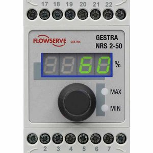
Indicators and adjustors
1 indicating & operating display,
1 green LED indicating standby-time (start),
1 amber LED indicating purging time (standby) 1 red LED indicating deactivation (stop)
Housing
Case for wall mounting with see-through lid, hinge and latch
Housing material: ABS, polycarbonate
Cable entry / electrical connection
1 14pole spring-loaded terminal strip, conductor size 2.5 mm2
cable gland with integrated
cable clamp 1 x M16 x 1.5
1 M12 female connector for sensor, with 8 poles
Protection class
2 (completely insulated)
Protection
IP 65 to EN 60529
Weight
approx. 1.3 kg
Further conditions:
Ambient temperature
when system is switched on: 0 ° … 55 °C during operation: -10 … 55 °C
Transport temperature
-20 … +80 °C (<100 hours), defrosting time of the de- energized equipment before it can be put into operation: 24 hours.
Storage temperature
-20 … +70 °C, defrosting time of the de-energized equipment before it can be put into operation: 24 hours.
Relative humidity
max. 95 %, no moisture condensation
Site altitude
max. 2000 m


