Technical data
Model and mechanical connection
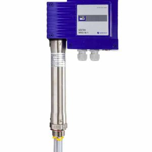
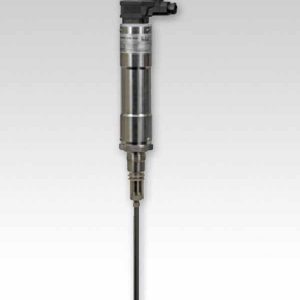
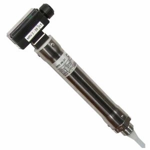
■ NRGT 26-2: Thread G3⁄4 A, EN ISO 228-1
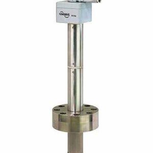
■ NRGT 26-2s: Flange DN 50, PN 40, DIN 1092-01
Nominal pressure rating, admissible service pressure and temperature
■ NRGT 26-2, NRGT 26-2s: PN 40, 32 bar (g) at 238 °CMaterials
■ Terminal box: 3.2581 G AlSi12, powder-coated
■ Sheath: 1.4301 X5 CrNi 18-10
■ Electrode rod insulation: PTFE
■ Screw-in body: 1.4571, X6CrNiMoTi17-12-2■ NRGT 26-2s:
◆ Flange 1.0460 P250GH
◆ Spacer disc PTFE
Max. installed length at 238 °C, all measurements in mm
- See “How to order”, tables in Fig. 1, Fig. 2
- Do not shorten the electrode rod.Measurement qualityThe information below applies to a compensated uid con- ductivity range from 100 – 10000 μS/cm based on 25 °C.
■ Reading error: +/- 1 % of set measuring range at the operating point
■ Resolution of reading on display: 0.1 %■ Resolution for internal processing:
15 bits with plus or minus sign (16 bits)
■ Resolution of 4-20 mA output:
15 bits equivalent to 0.49 μA/digitSupply voltage
■ 24 V DC +/-20 %Power consumption■ Max. 7 VA
Current input■ Max. 0.3 A
Internal fuse
■ T2A
Safety cutout at excessive ambient temperature
■ The cutout takes place at an excessive ambient tempera- ture of Tamb. = 75 °C
Analogue output
■ 1 x actual value output 4 – 20 mA, proportional to level, galvanically isolated
■ Maximum output load 500 Ω
■ M12 connector, 5-pole, A-coded