Function
Continuous controller
PID controller
Proportional band Xp: 1 to 9999
Integral time Ti [s]: 0.1 to 9999 s
Derivative time Td [s]: 0.1 to 9999 s
Switching controller
2 position (on-off) or 3 position stepping controller
The universal controller KS 92-1 is self optimizing, which means that the equipment itself tunes the optimum control parameters to the setpoint.
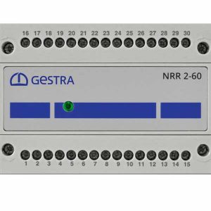
Design
Controller case in accordance with DIN 43700 for panel mounting and installation in control cabinets.
Wiring via screw-type terminals on back of housing. For conductor cross-section from 0.5 to 2.5 mm2.
Technical Data
Inputs
Controller input 1
Thermocouples

|
Type |
°C range |
|
B |
0/1820 |
|
C |
0/2315 |
|
D |
0/2315 |
|
E |
–100/1000 |
|
L |
–100/900 |
|
J |
–100/1200 |
|
K |
–100/1350 |
|
N |
–100/1300 |
|
R |
0/1760 |
|
S |
0/1760 |
|
T |
–200/400 |
Internal temperature compensation
Max. additional error: ± 0.5 K
Input impedance: ≥ 1 kΩ
Sensor break detection indicated on display, output of a safety value or detection of control output
Output
Relays
2 volt-free changeover contacts, output 1 and 2, switching capacity: 250 V, 2 A, resistive, 500 VA
Servomotor, output 3 and 4,
switching capacity 250 V, 2 A, resistive, 500 VA
Note
When connecting inductive loads, e. g. control contactors, make sure that the contactors are provided with RC suppressor circuits according to the speci cation of the manufacturers of the contactors in order to prevent high voltage spikes.
Current
0/4 – 20 mA max. load ≤ 500 Ω, output 4Voltage
0/2 – 10 V con gurable, load ≥ 2 kΩ, output 4
Alarm / Limit values
2 volt-free changeover contacts for upper and lower limit (absolute band and deviation alarm) with adjustable hysteresis
Switching capacity: 250 V, 2 A, resistive
Transmitter supply
18 V DC ± 20 %, not insulated
max. current 22 mA, max. load 600 Ω
Display
LED display: alphanumeric, three-lines “day & night” display, showing process values numerically or as a bar graph, with additional elements
Settings
Con guration, parameterization and operation via keyboard, menu-driven.
Housing
Panel mounting
Dimensions: 96 x 96 x 120 mm Weight: 300 g
Protection: IP 65 (front panel)
IP 20 (back)
Wiring
Interfaces: RS 422/485 (optional)
Voltage supply of measuring transducer: 24 V DC Max. admissible current: 22 mA
Mains voltage
Voltage range: 90 – 260 V AC, 48 – 62 Hz; 24 V AC/DC (optional)
Power consumption: 8 VA
Admissible ambient temperature: 0 °C – 60°C Storage temperature: –40 °C to 70°C
Rel. humidity: ≤ 75 % of annual average, must not be exposed to dew