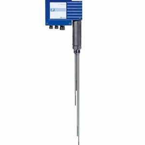
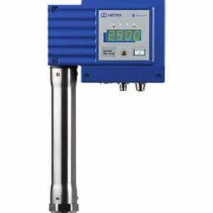
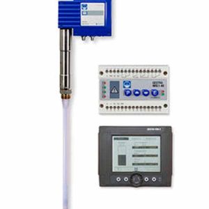
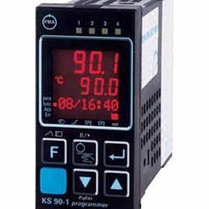
Bộ hẹn giờ xả đáy Gestra PRS 50
Technical data
Supply voltage
■ 24 V DC +/-20 %Power consumption
■ Max. 4 W
Current input
■ Max. 0.3 A
Required external fuse
■ M0.5A
Inputs
■ 1 x input for manual intermittent blowdown (external button)
■ 1x input for limit switch (volt-free) on intermittent blowdown valve
■ 1 x volt-free input 24 V DC (standby/burner)
for inputting an external switching command (intermittent blowdown OFF/burner active)
Outputs
Intermittent blowdown valve
■ 1 x volt-free relay contact (changeover relay)
Alarm output
■ 1 x volt-free N/O contact (as an alarm contact, open in the event of an error)
■ Maximum switching current
8 A at 250 V AC/30 V DC – cos φ = 1
■ Contact material AgNi0.15, AgSnO2
■ Inductive loads must have interference suppression
(RC combination) as per the manufacturer’s speci cation
Indicators and controls
- 1 x green 4-digit, 7-segment display for showing status information
- 3 x LEDs (2 x yellow, 1 x red)
◆ S/B yellow (standby/burner input active, depending on con guration)◆ yellow (intermittent blowdown valve open)◆ red (alarm)
■ 1 x 4-pole code switch for con guration (standby/burner function)
■ 1 x rotary knob with integrated push-button for setting parameters and executing the test function
Protection class
■ II double insulated
IP rating to EN 60529
■ Housing: IP 40
■ Terminal strips: IP 20
Electrical safety
■ Degree of contamination 2 for installation in control cabinet with protection rating IP 54, fully insulated
Admissible ambient conditions
Important notes
Connecting the 24 V DC power supply
The PRS 50 blowdown timer is supplied with 24 V DC. A safety power supply unit that delivers a Safety Extra Low Voltage (SELV) must be used to supply the equipment with 24 V DC.
Use an M0.5A fuse as an external fuse.
Connecting the output contacts (intermittent blow- down valve/alarm)
Use a slow-blow T2.5A fuse to protect the switching contacts.
Connecting the standby/burner input (24 V DC)
■ 24 V DC input, for external command intermittent blow- down OFF/burner active (standby/burner con guration).
■ Maximum cable length = 30 m.
Connecting the inputs (manual intermittent blowdown/
limit switch)
■ Connect a button (N/O contact) here if you require this function.
■ Connect the volt-free limit switch of the intermittent blowdown valve here.
■ Use a shielded, multi-core, twisted-pair control cable with a minimum conductor size of 0.5 mm2, e.g. LIYCY 2 x 0.5 mm2.
■ Apply the shield at both ends.
■ Maximum cable length = 100 m.
Air humidity:
* Only switch on after a 24-hour defrosting period
- Housing■ Housing material: Lower section of black polycarbonate (glass- bre reinforced), front of grey polycarbonate■ 2 x 8-pole terminal strips, removable separately■ Max. cross-section per screw terminal:
◆ 1 x 4.0 mm2 solid, or
◆ 1 x 2.5 mm2 stranded with sleeve, or◆ 2 x 1.5 mm2 stranded with sleeve
■ Housing attachment: Mounting clip on support rail TH 35 (to EN 60715)
Weight
■ Approx. 0.2 kg


