Technical data
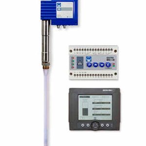
Conductivity controller LRR 1-50, LRR 1-51
Supply voltage
24 VDC, + / – 20 %
Fuse
external 0.5 A (semi-delay)
Power consumption
4W
Reset hysteresis
MAX limit: –3 % of the adjusted MAX limit, xed setting
Outputs
2 volt-free change-over contacts,
8 A 250 V AC / 30 V DC cos φ = 1
(continuous blowdown valve OPEN, OPERATING, CLOSED). 1 volt-free change-over contact,
8 A 250 V AC / 30 V DC cos φ = 1
(MAX alarm, switch-selectable).
Provide inductive loads with RC combinations according to manufacturer’s speci cation to ensure interference suppression.
1 analogue output 4-20 mA, max. load 500 ohm,
Actual value/manipulated variable Y (switch selectable)
Indicators and adjusters
1 rotary button with integrated pushbutton for parameter setting and testing MIN / MAX alarm
1 seven-segment LED display, four digits, green
1 red LED for MAX alarm,
2 amber LEDs indicating continuous blowdown valve opens/closes
1 four-pole code switch for con guration settings
Housing
Housing material: base: polycarbonate, black
Front: polycarbonate, grey.
Terminal strips separately detachable.
Fixing of enclosure: Mounting clip on supporting rail TH 35, EN 60715
Electrical safety
Pollution degree 2.
Protection
Housing: IP 40 to EN 60529
Terminal strip: IP 20 to EN 60529
with panel adaptor: IP 65 to EN 60529
Weight
approx. 0.2 kg
Further conditions:
Ambient temperature
when system is switched on: 0 … 55 °C, during operation: -10 … 55 °C
Transport temperature
–20 … +80 °C (< 100 hours), defrosting time of the de-energized equipment before it can be put into operation: 24 hours.
Storage temperature
–20 … +70 °C, defrosting time of the de-energized equip- ment before it can be put into operation: 24 hours.
Relative humidity
max. 95%, no moisture condensation
only conductivity controller LRR 1-50
Connection of conductivity electrode
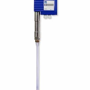
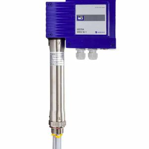
1 input for conductivity electrode LRG 1.-..
(cell constant 1 cm-1), 3 poles with screen or
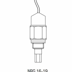
1 input for conductivity electrode LRG 16-9
(cell constant 0.5 cm-1), with integrated resistance thermometer Pt 100, 5 poles with screen
Measuring voltage
0.8 Vss, pulse duty factor tv = 0.5, frequency 20-10000 Hz.
Measuring range
1 to 10,000 μS/cm at 25 °C or 1 to 5,000 ppm at 25 °C.
Correction factor CF
adjustable between 0.05 and 5.000 in increments of 0.001
Calibration function CAL
Facilitates correction factor setting by entering the conductivity reading
only conductivity controller LRR 1-51
Connection of conductivity transmitter
1 analogue input 4-20 mA, e. g. for conductivity transmitter LRGT 1.-.., 2 poles with screen
Beginning of measuring range SinL
0.0 – 0.5 – 50.0 – 100.0 μS/cm, adjustable.
End of measuring range SinH
20.0 – 100.0 – 200.0 – 500.0 -1000.0 – 2000.0 – 3000,
0 – 5000.0 – 6000.0 – 7000.0 – 10000.0 – 12000.0 μS/cm, adjustable.