Technical data
Supply voltage
■ 24 V DC +/-20 %
Power consumption
■ Max. 5 VA
Current input
■ Max. 0.3 A
Required external fuse
■ 0.5 A M
Input/output
■ Interface for ISO 11898 CAN bus, CANopen, insulated
Inputs LRR 1-60
■ 1 x analogue input for potentiometer 0 – 1000 W, two-wire connection (display of valve position)
■ 1 x volt-free input 24 V DC (standby) for
inputting an external switching command,
Control OFF/Valve CLOSED/Intermittent blowdown OFF
Outputs of
MIN/MAX contacts/Control valve (OPEN/CLOSED)
■ 4 x volt-free relay contacts, contact material AgNi0.15, AgSnO2
Con gurable as:
◆ MIN/MAX alarm or MAX alarm and MIN relay as automatic intermittent blowdown
◆ Continuous blowdown valve (CLOSED/OPEN)■ Maximum switching current – 8 A at 250 V AC/
30 V DC – cos φ = 1
■ Inductive loads must have interference suppression
(RC combination) as per the manufacturer’s speci cation.
Analogue output
■ 1 x actual value output OUT 1: 4 – 20 mA, e.g. for an actual value display
■ Max. load resistance 500 WIndicators and controls
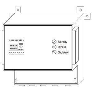
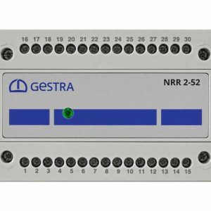
■ 1 x multicolour LED (orange, green, red)
◆ orange = power up◆ green = running◆ red = malfunction
■ 1 x 4-pole code switch for setting the controller group and baud rate
Protection class
■ II double insulated
IP rating to EN 60529
■ Housing: IP 40
■ Terminal strip: IP 20